Three modes, chosen by the accelerometer.
Every angle was simulated in Autodesk Fusion CFD before anything got printed. The plots are the airflow through the wing at each one.
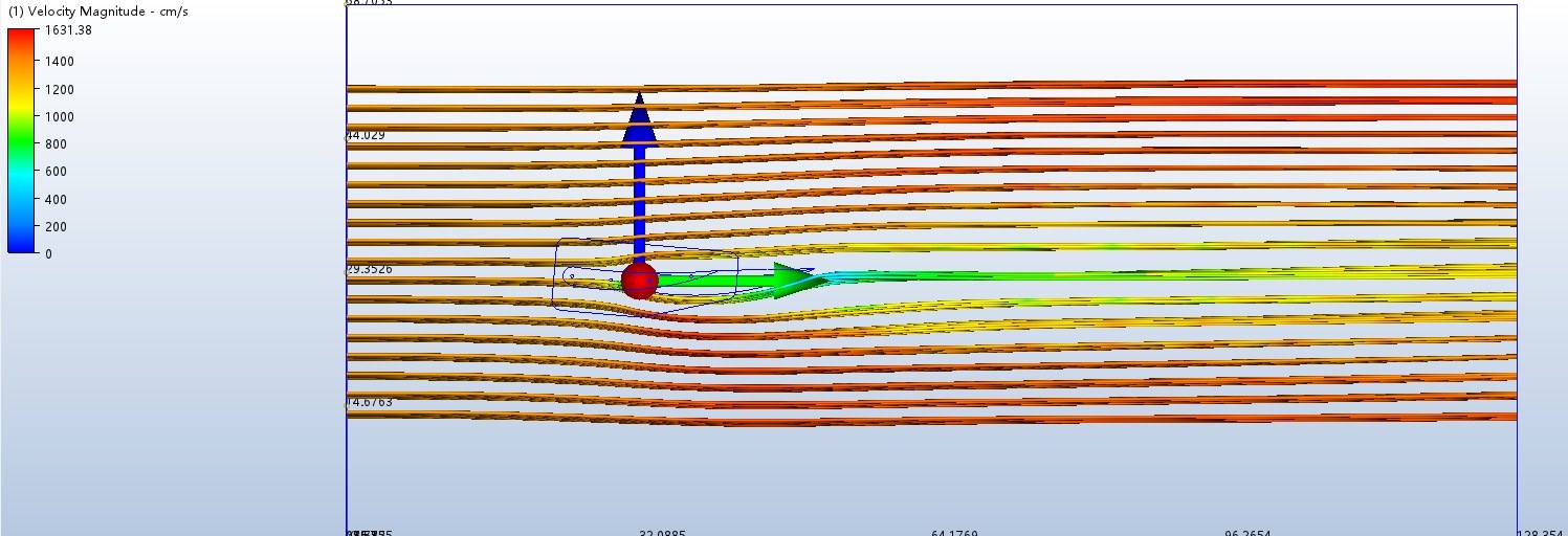
Under throttle: the wing lies almost flat so it is barely fighting the air. The least drag of the three, which means quicker acceleration and a higher top speed.
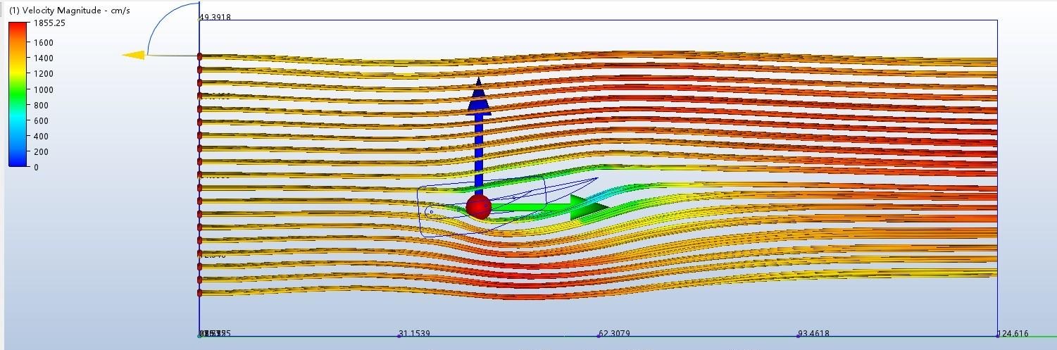
Holding a steady speed: a small angle buys real grip for almost no drag. Ten times the downforce of neutral for less than a newton more, which makes this the efficient one.
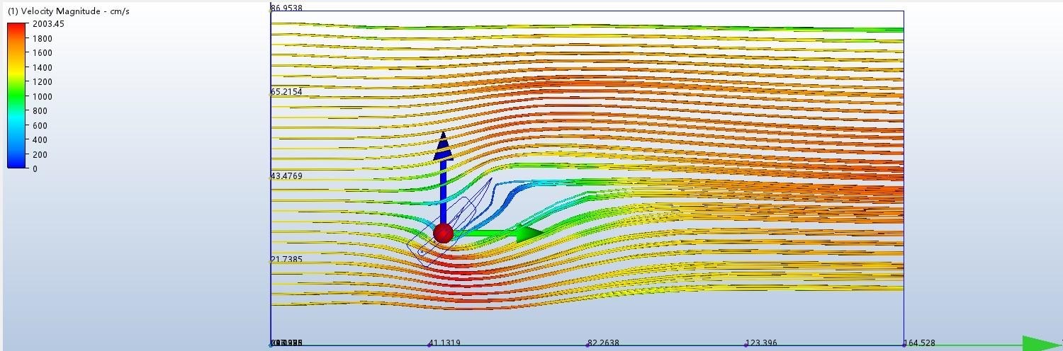
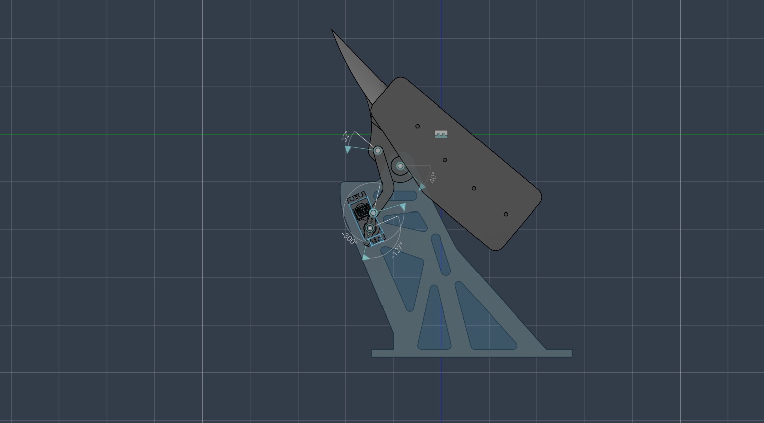
Under braking: the wing stands up into the air and becomes a brake. Maximum downforce to plant the car, plus a wall of drag that helps slow it down.
What the simulation actually said.
| Mode | Angle | Trigger | Downforce (N) | (lb) | Drag (N) | (lb) | D/D ratio |
|---|---|---|---|---|---|---|---|
| Neutral | −5° | accel > +0.09 g | 88.4 | 19.9 | 9.4 | 2.1 | 9.4 : 1 |
| Cruise | +5° | |accel| < 0.07 g | 882.4 | 198.4 | 10.3 | 2.3 | 85.7 : 1 |
| Airbrake | +40° | decel > 0.07 g | 1,708.8 | 384.1 | 262.0 | 58.9 | 6.5 : 1 |
Swipe the table sideways for the rest of the columns.
All three runs at a 30 mph (13.4 m/s) inlet, air at standard conditions (ρ 1.205 kg/m³, μ 1.817×10⁻⁵ Pa·s), steady-state incompressible, k-epsilon turbulence with mesh refinement at the wing surface. Reynolds numbers ran 772,398 at +5° to 1,153,020 at +40°, fully turbulent across every case. Forces taken from the fluid-forces-on-walls output.
Opening from neutral to cruise multiplies downforce roughly tenfold and costs under a newton of drag. The full sweep to the airbrake is the dramatic one, 1,620 N more downforce and 253 N more drag end to end, but that angle only runs while you are actually on the brakes. The car spends most of its life at cruise, so that is the angle that has to be worth having.
Why the wing has to move.
Downforce and drag pull against each other. Set a wing up for grip through a corner and it holds the car back down the straight. Set it up for a low-drag top speed and it gives you very little when you actually need the rear planted. Every fixed wing bolted to a car picks one point on that trade and stays there for the life of the car.
This one does not pick. An accelerometer on the wing reads how hard the car is accelerating or slowing, and the wing moves to the angle that suits what the car is doing right then: flat under throttle, a shallow angle at cruise, and fully up under braking.
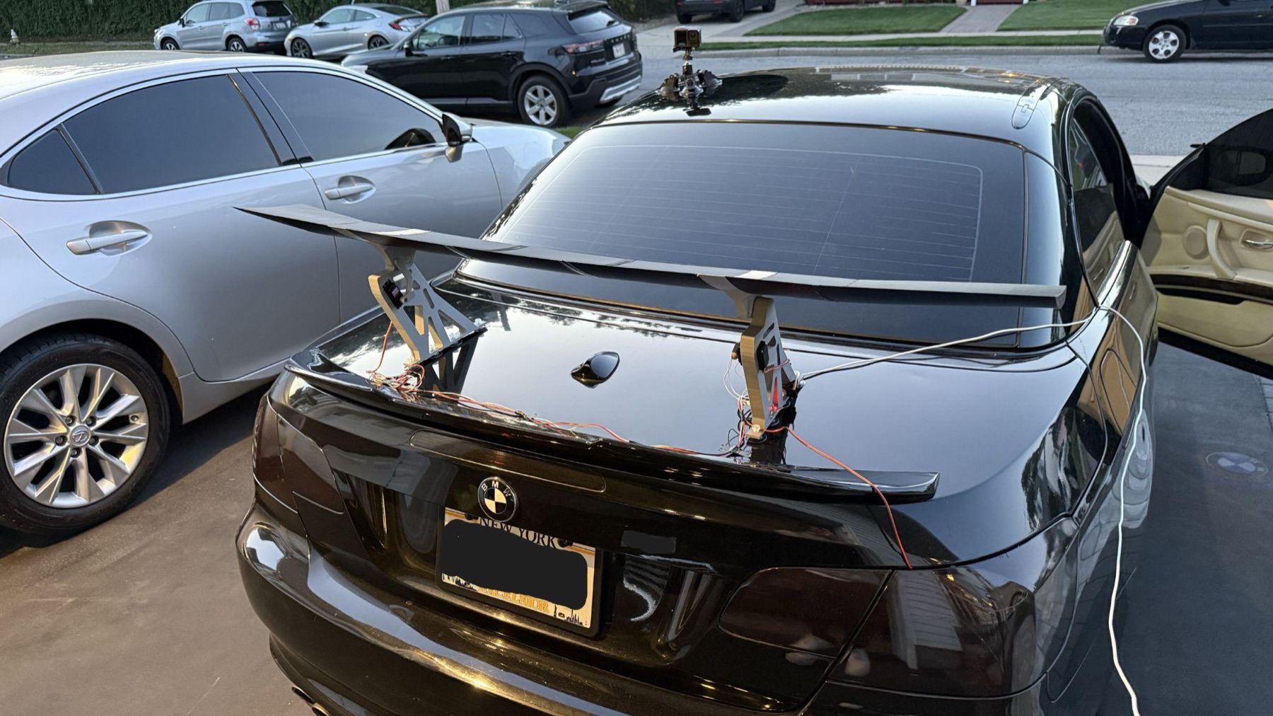
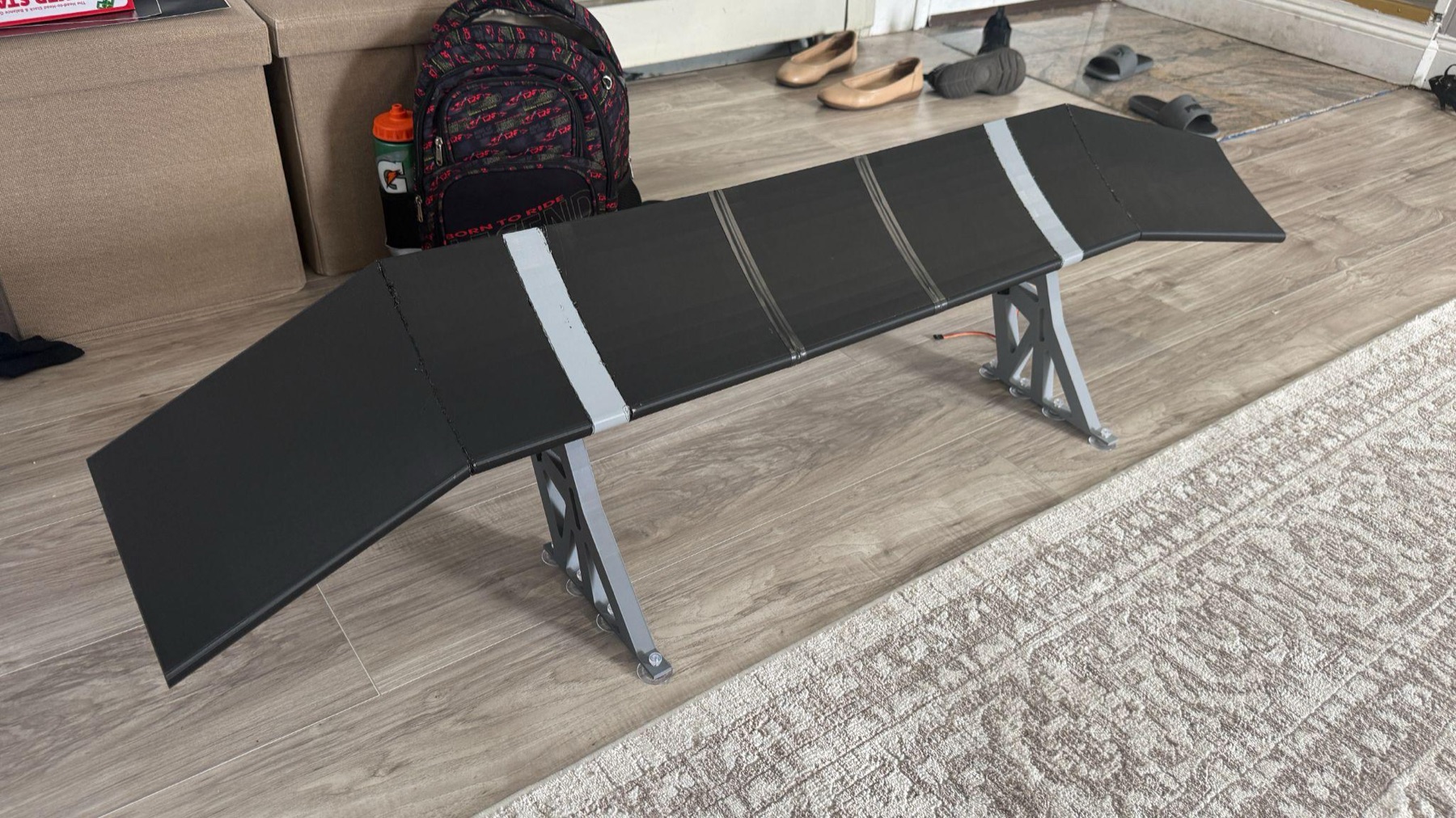
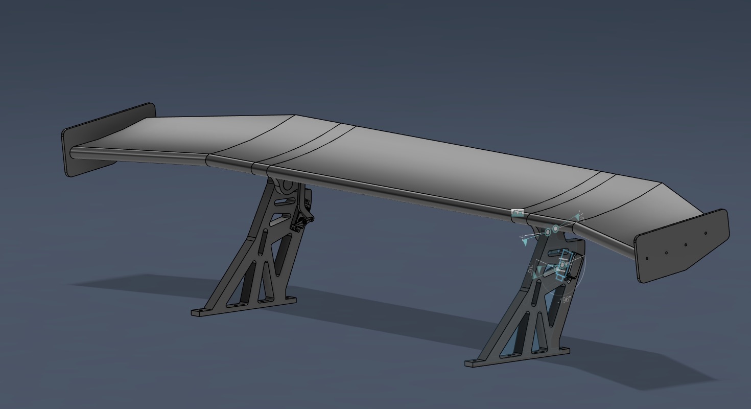
The finished system on the development car. The whole assembly (wing, brackets, servos, electronics and its own battery) mounts to the trunk lid on suction cups and comes off without leaving a mark.
Two references, one of them airborne.
The variable-incidence idea is borrowed from the Vought F-8 Crusader, the only production aircraft that pivoted its entire wing rather than its control surfaces. It raised the wing's incidence for carrier landings so the fuselage could stay level. The second reference is the Zenvo TSR-1, whose rear wing tilts laterally through a corner to generate a yaw-stabilising moment.
The closest everyday relative is F1's DRS, which flattens the rear wing on designated straights to shed drag. AVIWS does the same thing under acceleration, then adds the mode DRS doesn't have: a third, high-angle position that deploys the wing as an active braking aid.
The profile had to make downforce at a shallow angle.
The section started as a standard cambered airfoil, mounted inverted so the pressure differential works downward. It was then modified: more curvature on the upper surface to accelerate the flow and drop the static pressure, and a flatter lower surface to hold a higher-pressure region underneath.
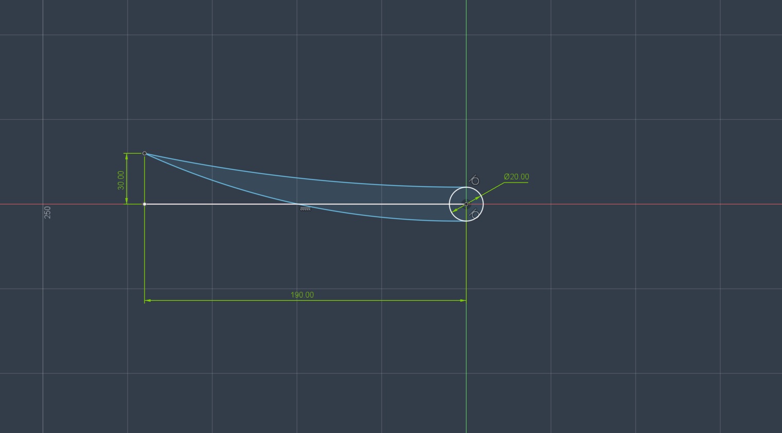
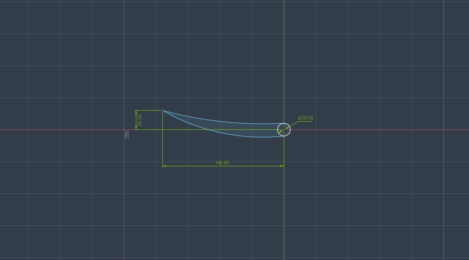
1,400 mm of span, in three aerodynamic sections.
A 900 mm centre section carries the constant profile and does the bulk of the work. Either side of it, a 250 mm outboard section lofts from the centre profile at its inboard end to a higher-angle profile at the tip. That puts more downforce toward the tips and improves spanwise load distribution, with no hard geometric break to trip the flow.
Endplates close both tips. They stop high-pressure air migrating around the wingtip to the low-pressure side, which is what generates induced drag and bleeds away effective lift. They also double as the structural mounting interface, with M3 heat-set inserts moulded straight into the print so nothing needs a nut on the back face.
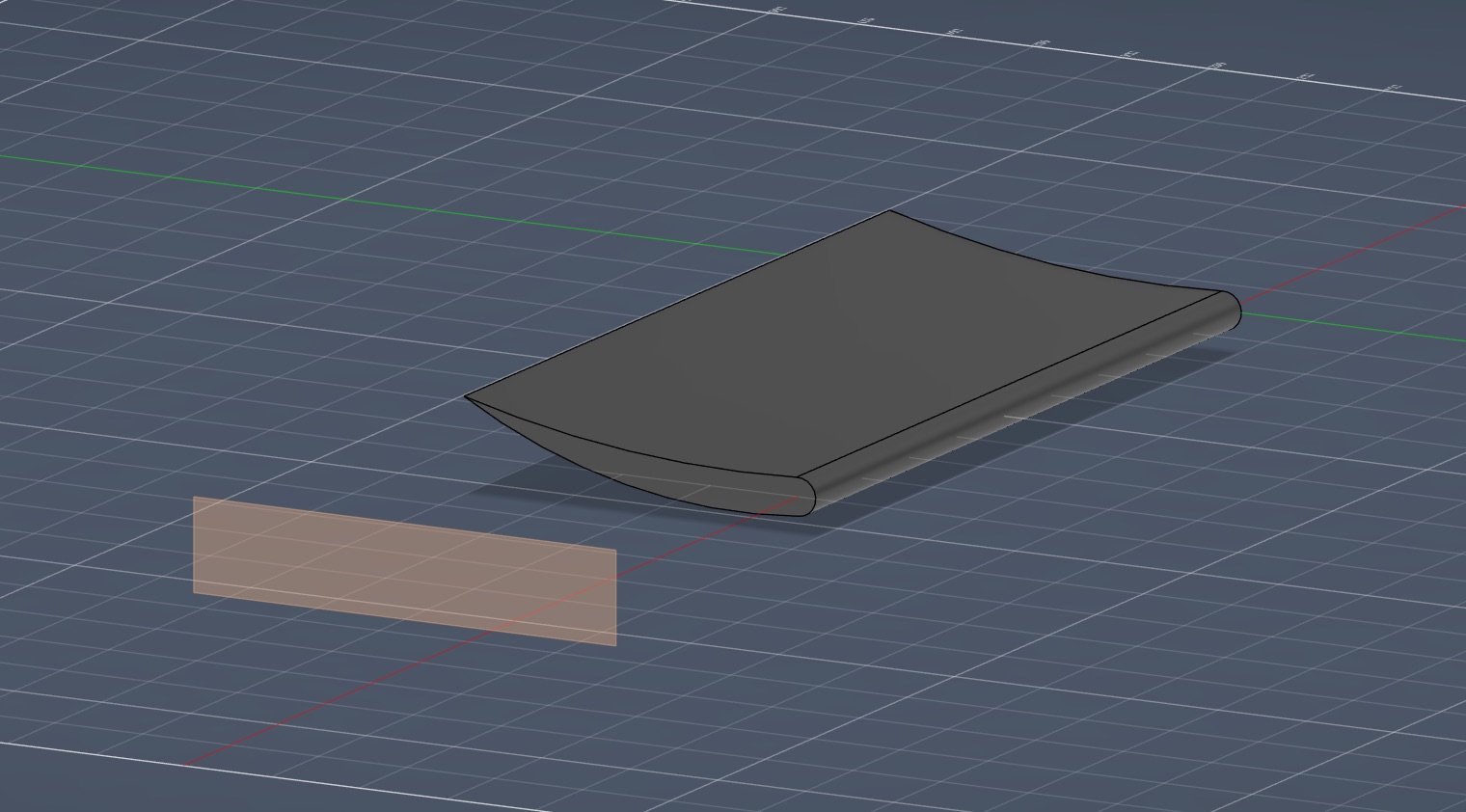
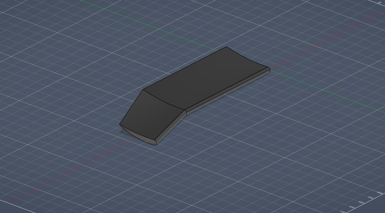
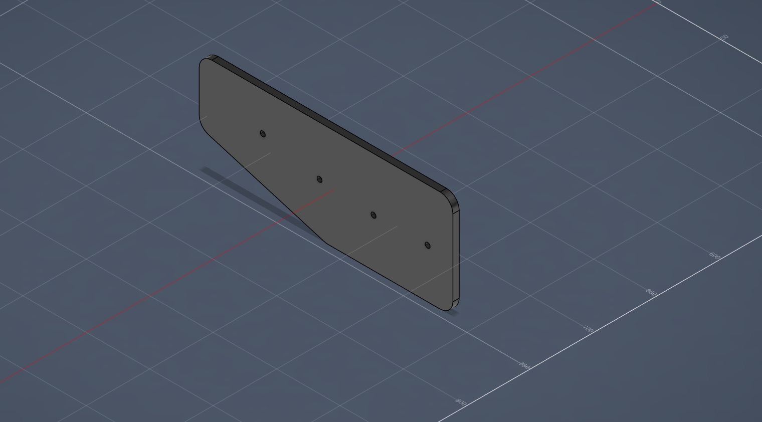
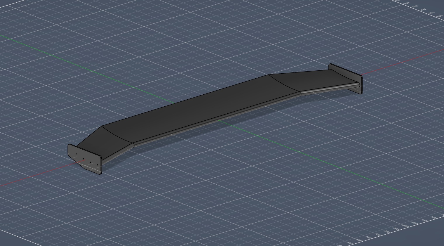
The plan was foam and fibreglass. It didn't survive contact.
The original fabrication route was XPS foam: hot-wire the profile using printed templates pinned to each face of the block, stack the slices, fair the surface against a printed two-part female mould, then laminate it in 4 oz fibreglass and marine epoxy.
It got abandoned before it started. Hot-wire cutting is only as good as the hand guiding it, and any deviation propagates through every slice in the stack. Fairing foam to a CAD-defined profile is slow and has no guaranteed dimensional accuracy, and lamination adds its own variables on top.
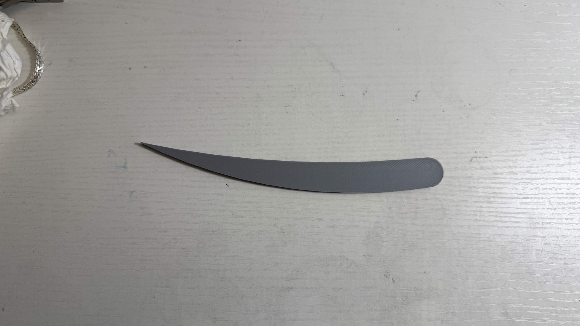
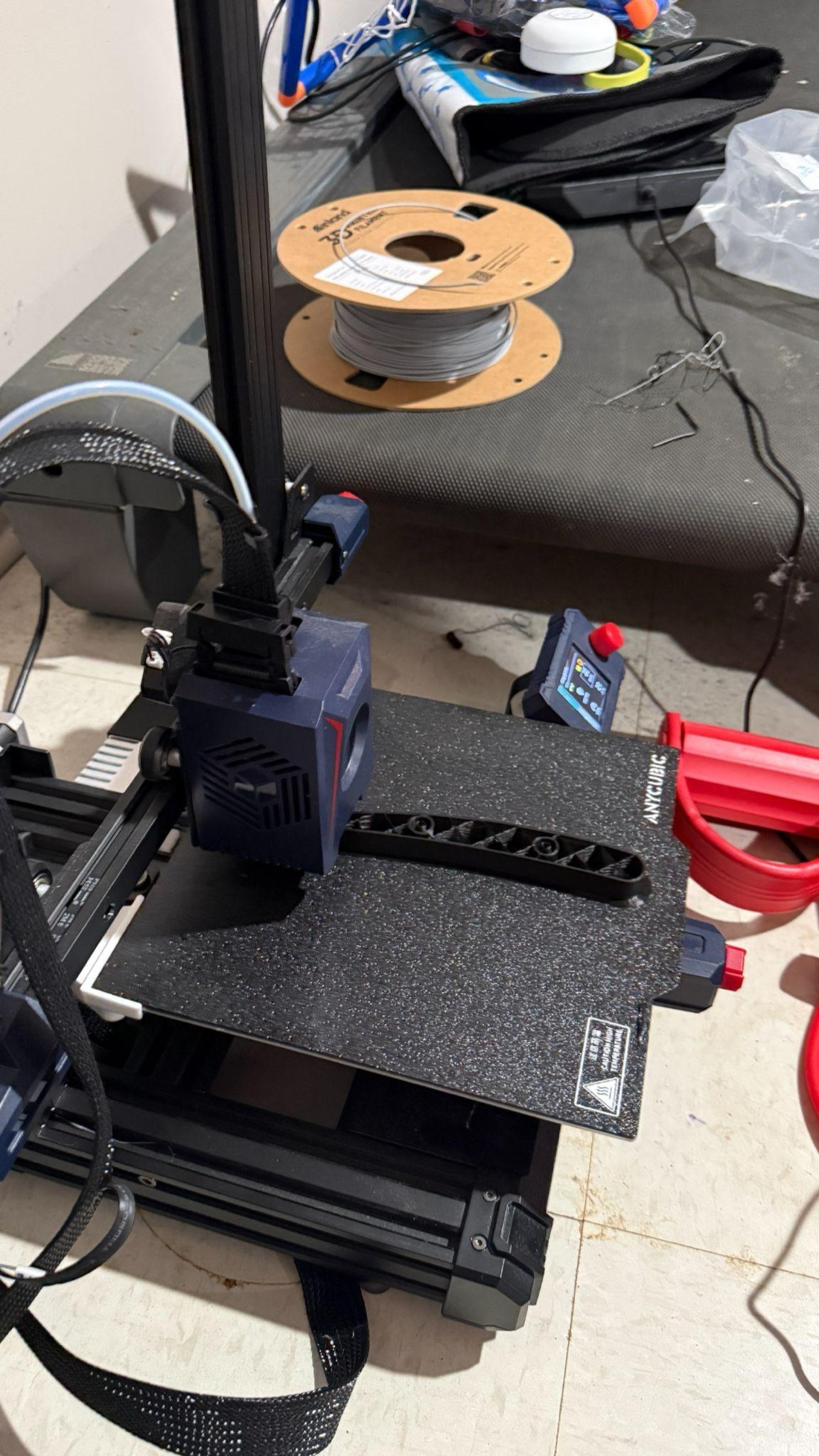
Switching to FDM traded mass for precision, and the trade was worth making. Every part comes off the bed as the CAD file drew it, and the features that would have been miserable to build into a foam core (hinge bores, dowel holes, heat-set insert pockets, servo mounting geometry) are simply part of the print. PLA for the structural components, chosen for dimensional stability and stiffness at these speeds.
Printed in 200 mm pieces, then welded into one.
No consumer printer swallows a 1,400 mm span, and a monolithic wing would mean reprinting the whole thing to fix any part of it. The centre element is split into 200 mm modules, joined on 10 mm dowel pins in bored holes on each mating face. The dowels hold spanwise alignment and carry shear across the joint, so the assembly loads as one continuous element instead of a chain of segments.
Then every external seam was plastic welded: a soldering iron run along the joint melts and intermixes the PLA on both sides, fusing the modules into a single structure. Dowels do alignment and shear; the weld does continuous spanwise rigidity.
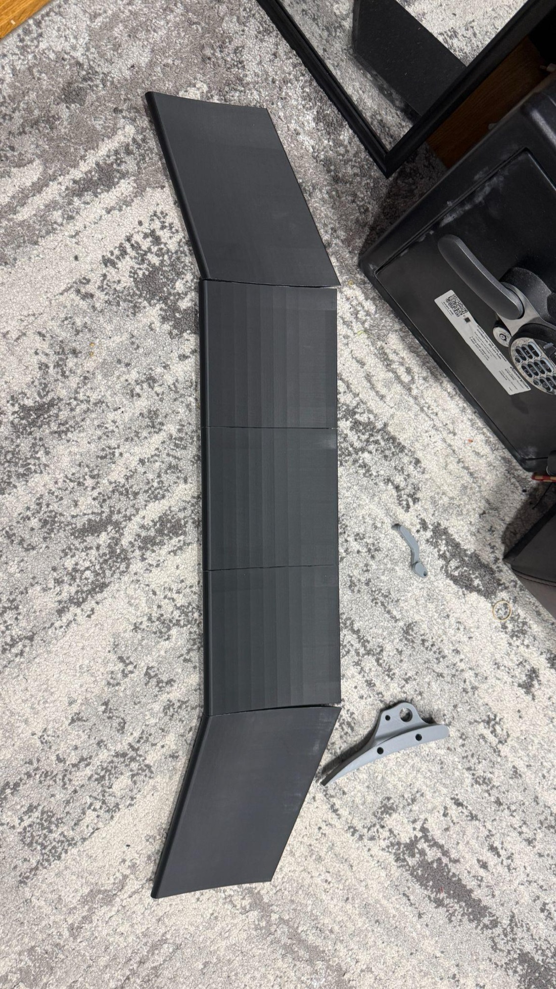
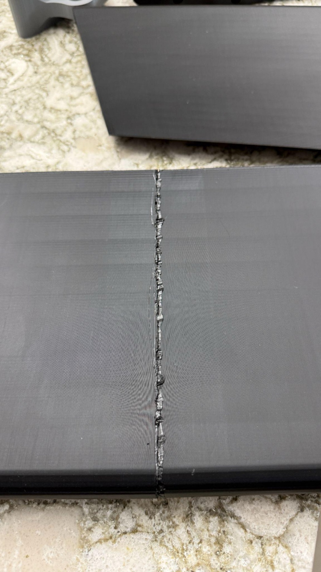
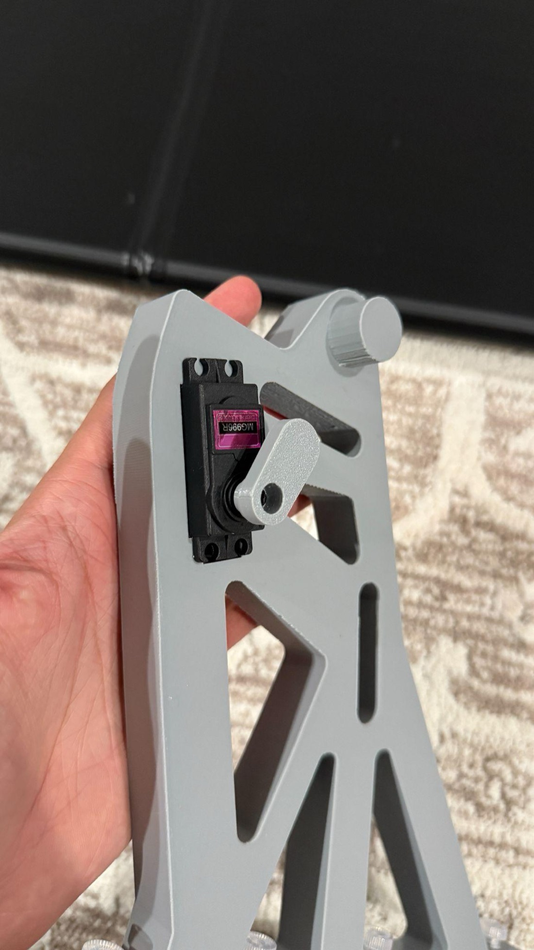
Direct drive, because a pushrod would flex.
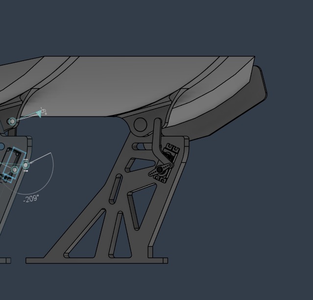
Two DS3218 servos, rated 20 kg·cm stall at 6 V with full metal gears, sit in pockets in the support brackets with their output shafts on the wing's hinge axis. Metal gears were non-negotiable: aerodynamic hinge moment scales with the square of velocity, and at highway speed a wing this size will strip or back-drive the plastic gears in a hobby servo like an SG90 rated at 1.8 kg·cm.
The servos drive the wing through a custom-designed horn rather than a generic one, to kill the angular slop that shows up when an off-the-shelf horn meets a third-party spline. Direct drive was chosen over a pushrod linkage because a slender rod resisting that hinge moment is a buckling risk exactly when you need it most: in the airbrake position, at maximum load.
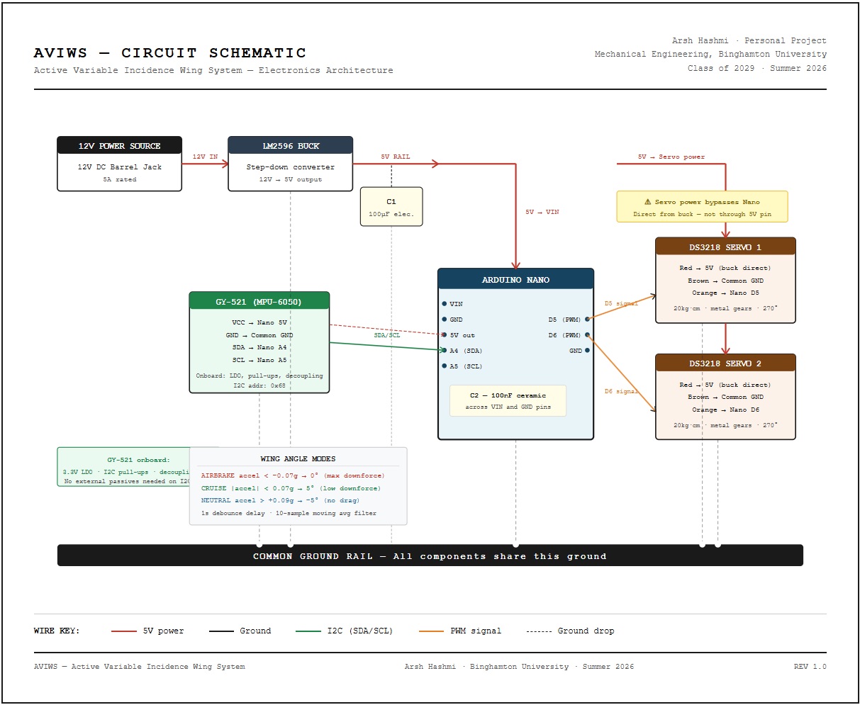
Five components, and reasons for each.
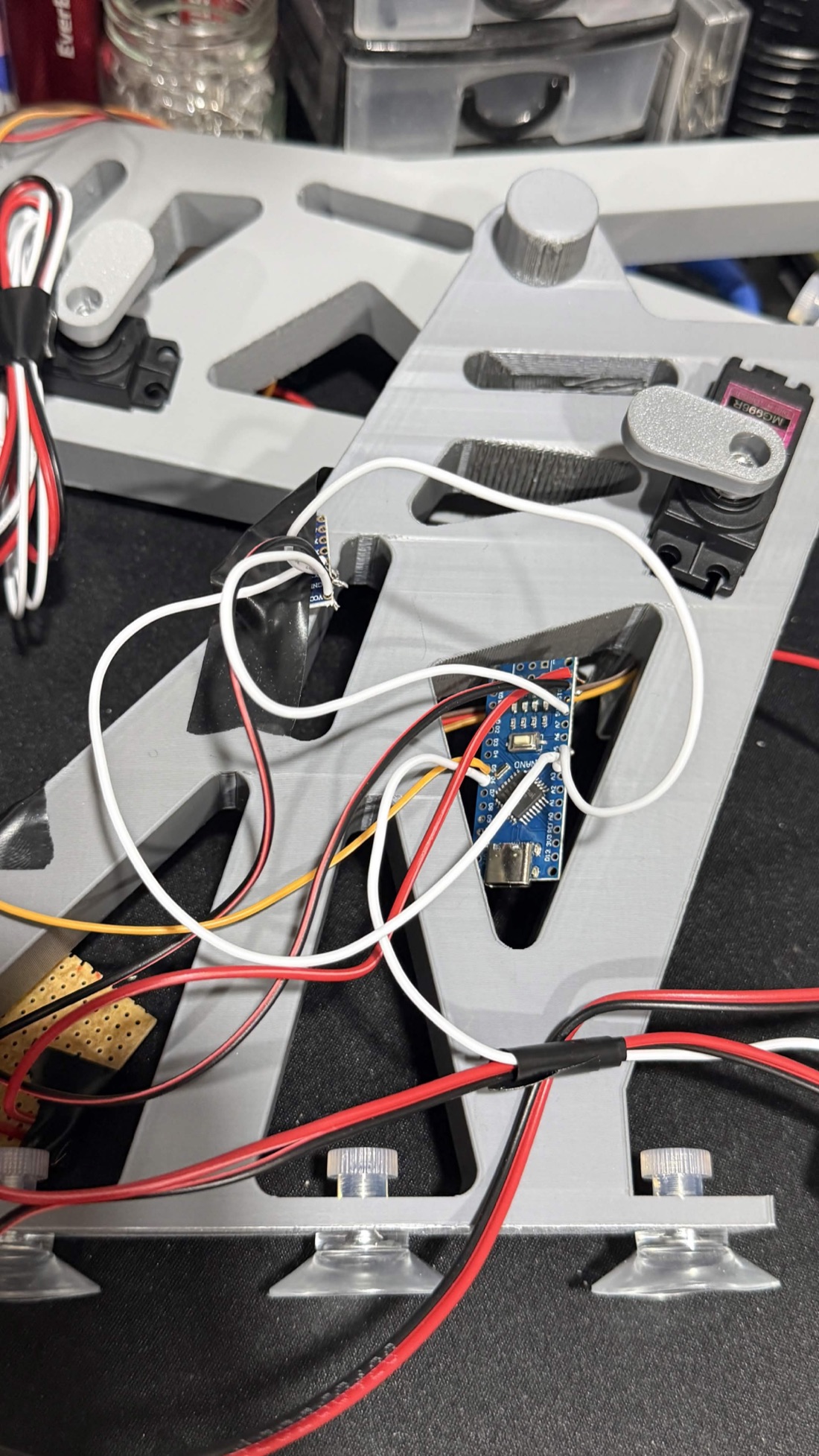
The brief for the electronics was the fewest parts that would do the job reliably. An ESP32 has more of everything, but a single-axis loop with two inputs and one output doesn't need dual cores or WiFi, and reliability scales inversely with part count. The whole assembly is recessed into the bracket's lattice rather than boxed separately, wiring zip-tied at intervals so nothing moves under vibration.
One deliberate detail: the servos are fed straight from the buck output rather than through the Nano's onboard 5 V pin. A loaded DS3218 can pull over an amp, which the Nano's regulator is not rated to supply, so routing around it removes an entire failure mode.
A three-state controller, and a one-second fuse.
Raw 16-bit accelerometer over I²C, divided by 16,384 for the ±2 g full-scale range.
Subtract a 0.07 g offset: gravity bleeding into the longitudinal axis from an imperfect mounting angle, measured stationary and level.
Ten-sample moving average in a circular buffer, to kill engine vibration, road inputs and buffeting off the wing itself.
A new mode has to hold for a full second before it's executed. Any reversion resets the timer.
→ Neutral, −5°. Under throttle, get out of the way.
→ Cruise, +5°. Holding speed, hold baseline downforce.
→ Airbrake, +40°. Braking, deploy everything.
The loop polls at 50 ms, a 20 Hz update rate. That's far faster than it needs to be: aerodynamic loads on a street car shift over hundreds of milliseconds, and the one-second debounce, not the polling rate, is what actually sets how quickly the wing responds. The filter itself adds about 500 ms of lag, which sits comfortably underneath that.
Bench first, then a real road.
On the bench: an I²C scan to confirm the MPU-6050 at address 0x68, each servo driven individually and then together to verify the mirrored position logic, the IMU tilted by hand along each axis to identify the longitudinal one, and the filter checked by tapping the sensor to confirm brief impulses didn't cross a threshold.
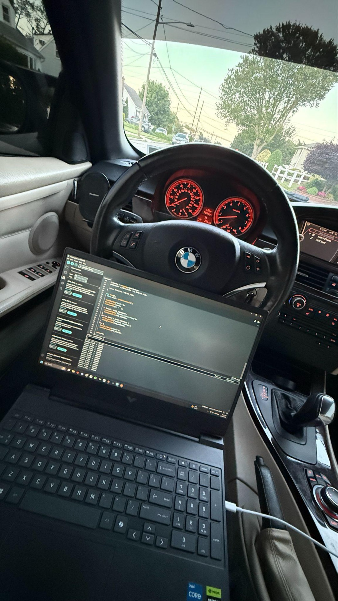
Then the whole thing went on the trunk lid of a 2011 E93 on suction cups, chosen precisely because they leave the car untouched and move to any other car without refabricating anything. A laptop ran into the cabin on a USB lead for live serial, and a GoPro on the roof watched the wing.
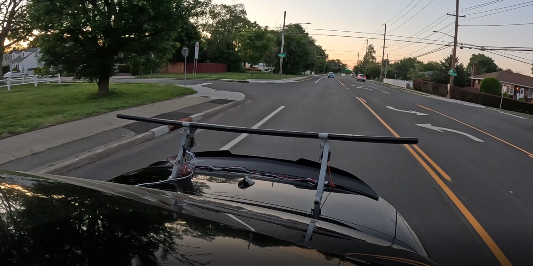
It worked. The wing flattened under throttle, settled back to cruise at steady speed, and deployed fully under braking, at the points in the acceleration profile it was supposed to. The one-second debounce turned out to be the critical detail. Earlier firmware without it hunted between modes on road undulations, gear changes and small throttle inputs. The thresholds proved sensitive enough for ordinary street driving without needing to be provoked. The suction mount didn't move.
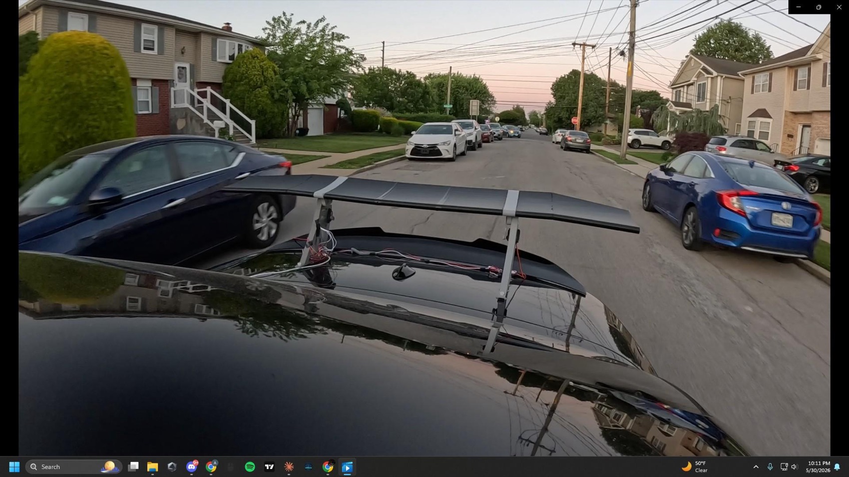
And then something broke.
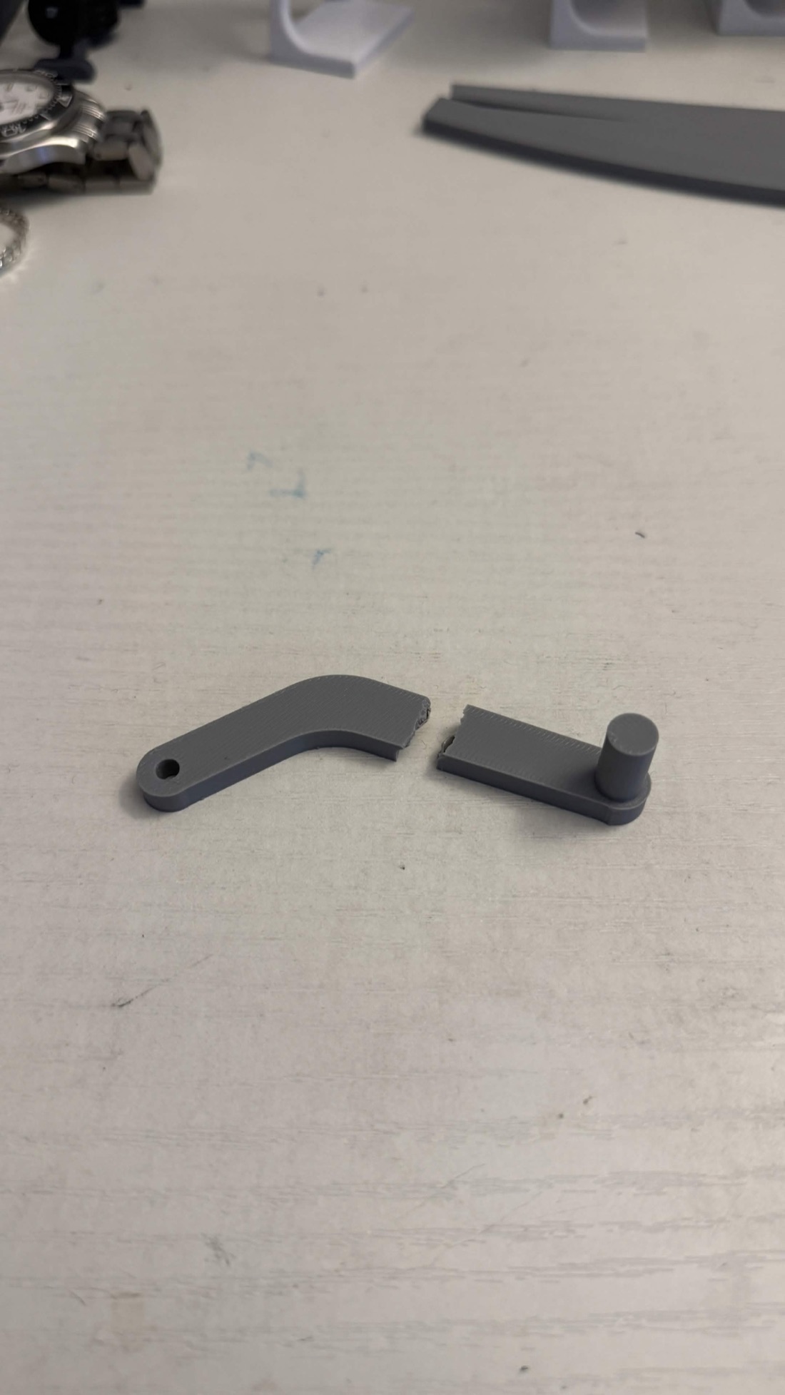
This is a part-level mistake with a part-level fix, and it is first in the queue for the next revision: more wall thickness at the failure location, a larger fillet radius at the stress concentration, and probably CF-PLA for that one component to buy stiffness without much mass. Nothing about the architecture needs to change.
Where it goes from here.
The architecture was drawn with the second axis in mind from the beginning, which is why the IMU's full six degrees of freedom are read even though the controller currently uses exactly one of them.
Built solo, in a week, with a consumer 3D printer and off-the-shelf parts. The core system works, the one failure mode is understood, and the next iteration is already specified.